Operation and Diagrams
(see diagrams and illustrations on bottom)
SEQUENTIAL TURN SIGNAL CIRCUIT OPERATION
The sequential turn signal circuit is unique in its operation. The
stoplight circuit will also be covered since it is wired into the turn
signal circuit.
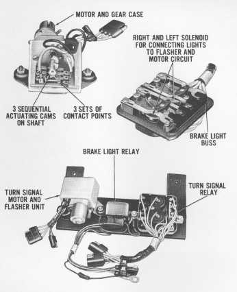
The basic components (Illus. 17001.3- 10) of the s~juentia1 turn signal
and stoplight circuits are the turn signal switch, mounted on the steering
column; the turn signal indicator relay, mounted on the steering column
support hracket the stoplight switch, mounted on the brake pedal support,
and the turn signal relay, stoplight relay and turn signal flasher and
motor unit which are wrapped in soundproof insulation and mounted in the
luggage compartment behind the left fender trim panel.
The flasher assembly consists of a motor, three cams on a shaft and
three sets of contact points. The three cams axe staggered and each set
of contacts is connected to one of the three rear light bulbs through the
turn signal relay.
When the turn signal switch is actuated, either right or left, a circuit is completed to the turn signal relay to the respective right or left side solenoid. A set of four contact points is actuated by the solenoid to connect the rear lights to the flasher and motor circuit. Three contacts connect the three rear lights and one contact connects the front turn light.
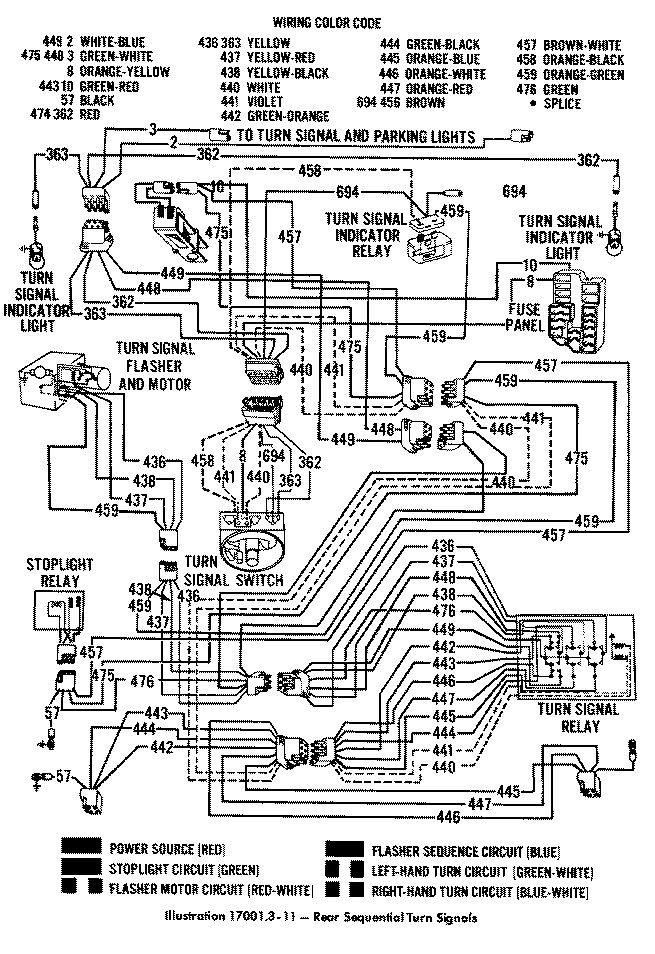
The following wires are connected together at the turn signal switch when the switch is put in the right- hand position: (694, 362) and (8, 441, 458). In the left-hand position, wires (694, 363) and (8, 440, 458) are con nected together.
When the turn signal switch is actuated, either right or left, the circuit is completed to the flasher motor and to the flasher cam contacts. This starts the motor in operation and the cams begin to rotate. As the cams rotate, the three sets of contacts are closed in sequence and the three rear lights are illuminated in sequence beginning at the inboard light, then the center light and then the outboard light. All three lights go out at the same time and the cycle is repeated, as long as the turn signal switch is closed to indicate a turn. The front parking light bulb flashes at the same time as the center rear bulb.
When the turn signal switch is canceled, the light bulbs go out immediately.
The turn signal indicator lights are controlled by the turn signal indicator relay (a current relay). The relay is adjusted so that it will open a set of contacts whenever the four turn signal light bulbs are on. The relay remains closed and the indicator light is illuminated until the four signal lights are all on and current flow is heavy enough to cause the contacts to open, The relay contacts then open and the indicator light goes out until all four exterior lights are off simultaneously. The relay contacts then close to illuminate the indicator light If one or more of the exterior light bulbs are not functioning (burned Out), the relay contacts will remain closed and the indicator light will remain on.
The brake light circuit in this sequential system is connected into the circuit differently than in the standard turn signal circuit. In the standard circuit, the brake lights are connected to the turn signal circuit at the turn signal switch. In the sequential system, the brake lights are connected to the turn signal circuit in the turn signal relay. When the turn signal switch is in the neutral position, no electrical connection is made at the turn signal switch and the turn signal relay solenoids are at the rest position. Six contact points in the turn signal relay are connected electrically together and complete the circuit from the brake light switch, through the stoplight relay* to the spotlights.
The wiring schematic for the exterior lights, turn signals and emergency flasher systems is included in the Electrical Diagrams Section.
TESTS
Refer to Illus. 17001.3-11 for the wiring schematic~
ONE LIGHT, EITHER FRONT OR REAR, DOES NOT OPERATE
First, eliminate the possibility of any problems which can be found by a visual inspection and the possibility of a burned- out bulb. The only possible part left to check is the turn signal relay in the taped package.
If the bulb and socket and wiring has continuity to the turn signal relay and all of the lights but one operate, then make a test for power at the relay terminal of the bulb in question. If no power is available, the turn signal relay switch mechanism is defective. This test is made with the ignition switch ON and the turn signal switch in the proper position.
ONE SET OF TURN SIGNAL LIGHTS DOES NOT OPERATE BRAKE LIGHTS OPERATE
This problem can be isolated to the turn signal switch, the turn signal relay or the wiring from the switch to the relay.
Make a test for power at the turn signal switch disconnect terminals with the turn signal switch in the posi tion in question and the ignition switch ON. If there is no power at the terminals leading to the motor, turn signal indicator relay, or the turn signal relay; the turn signal switch is defective. If power is available to all these ter minals, the trouble can be isolated to the wire leading to the turn signal relay coil or to the relay unit itself. Make a test for power at the turn signal relay disconnect at the terminal leading from the switch. If power is not avail able, the wiring has a defect between the switch and the relay. If power is available, the turn signal relay is defec tive. The wire in question leads to the coil in the relay which actuates one side of the relay and switches the circuit from the stoplight wires to the turn signal wires.
* The stoplight relay was only used on early production.
ONE OR BOTH SETS OF STOPLIGHTS DO NOT OPERATE TURN SIGNAL LIGHTS OPERATE
If one set of brake lights does not operate and the turn signals do operate, the problem has to be a defective turn signal relay.
If all stoplights do not operate, the problem can be at the stoplight switch, stoplight relay, turn signal relay or the wires leading between the three components.
Make a test for power across the stoplight switch terminals with the brake pedal depressed. If there is no power, the stoplight switch is defective. If there is power, make a test for power at the stoplight relay to determine if it has a good ground connection and if it is operating. If there is no power, there is a defect in the wiring be tween the stoplight switch and the stoplight relay, If there is power and the relay is functional, check the wire and its connections between the stoplight relay and the turn signal relay. If the wire is good, there is a defective con -nection inside the turn signal relay.
ALL TURN SIGNAL LIGHTS DO NOT OPERATE ALL PARKING LIGHTS AND STOIPLIGHTS DO OPERATE
This problem will require visual, audible, and power tests at all of the sequential turn signal components. Since the stoplights operate, we can temporarily eliminate the turn signal relay as the trouble spot Using the circuit diagrams as reference, make tests for power at the turn signal switch first in both left and right positions to determine if power is available from it to the turn signal indicator relay, the flasher and motor unit and the turn signal relay. All tests are made with ignition and turn signal switch ON. After eliminating the turn signal switch as the trouble spot, test for power at the turn signal indicator relay to determine if it is operating properly. Next, go to the flasher and motor unit and test at all of its leads for power. The last possible unit is the turn signal relay.
Test the components in the above mentioned order, namely:
1. Turn signal switch
2. Turn signal indicator relay
3. Flasher and motor unit
4. Turn signal relay
Test the components power source lead(s) and then the power outlet lead(s) before assuming the component is defective, because the trouble may be in the wiring between components.
EMERGENCY WARNING FLASHER
DESCRIPTION
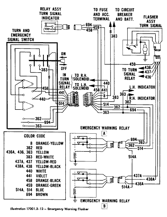
The emergency warning flasher circuit utilizes the sequential flasher and motor unit as the flashing element instead of a heavy-duty flasher can. In addition, the system requires Only two double-pole relays versus three relays in the past system.
As shown in the flasher and motor unit schematic, one set of contact points and one operating cain has been eliminated. This set of contacts was used as the parking switch for the sequential motor, the motor will now park in any position.
The switch for the emergency warning flasher circuit has been relocated to the right-hand side of the steering column, opposite the turn signal switch lever. Both switches are in fact a one unit assembly.
As in the past, the turn signal circuit can only be operated when the ignition switch is in the ACO position or the ON position. The emergency warning flasher circuit receives power directly from the battery through a sepa rate circuit breaker and can be operated independently of any other circuit
Illustration 17001.3-12 shows the necessary components and wiring for
the emergency warning flasher circuit The switch is shown in OFF position
and the relays in the de- energized position.
OPERATION
When the switch is pushed in to the ON position, several circuits are completed:
1. Wire 441 completes the circuit to the right-hand solenoid in the turn signal relay. This connects the right-hand front and rear lights to the flasher motor circuit.
2. Wire 440 completes the circuit to the left-hand solenoid in the turn
signal relay. This connects the left-hand front and rear lights to the
flasher motor circuit.
3. Wire number 514 opens the circuit through the coils of relays A
and B. This de-energizes the relays (if the ignition switch is ON) and
closes the contact points. NOTE: These two relays are energized when the
ignition switch is in ACC or ON position, when energized the contact points
open.
4. Wire number 458 completes the circuit through the coil and contact points of the turn signal indicator relay. Wire 459 in turn completes the circuit to the flasher motor and starts it turning.
o. Wire 694 completes the circuit through the contact points of relay A and on through wires 362 and 363 to the right- and left-hand indicator bulbs.
6. Since the contact points of relay B are closed, wires 4364 437A and 438A are in effect a single wire circuit This is done to combine the three sequential signals, coming from the flasher, into a single flashing signal.
The flashing signal is then sent through the closed points of the turn
signal relay to all six rear lights and two front lights. The two indicator
lights on the dash panel go out each time the current draw from the eight
exterior lights causes the turn signal indicator relay contact points to
open. The indicator lights flash at the same speed as the exterior lights,
but at opposite times.
--------------------------------------------------------------------------------------------------------------------
If you wish to convert your mechanical switching unit to an electronic one, I have these available for $129.95
drop me an email for more information at jdrax@tbirdranch.com
=======================================================================