
brought to you by:
Thunderbird Ranch
---index to tips---
Shift Lever Fix-It for all Thunderbirds from '58 thru 1966
Steering Column Bushing Replacement
Removing broken off bolts
Vinyl Roof Covering Installation
Headliner Replacement in Town Landau and Town Coupe
Non - operational Power Windows
Exhaust Manifold Tips
FMX Transmission Tech Tips
C-6 Transmission Tech Tips
Too much top end oiling
Throttle Linkage Trouble (w/pic)
Broken Button on Power Seat Switch
Polishing Plastic Lenses
67 Ash Tray slide fix
Foamy Steering Fluid / Growling Noise / Air in System
Removing Frost Plugs Easily
Brake fade and/or soft pedal
Dual Master Cylinder Conversion for 1964
Water Leaking into the Trunk - 64-66
Re-Upholstering 1958-59 Door Panels
Rebuilding the seat foam in the 1958-60 Birds
1965 thru 1968 Sequential Turn Signals
1970-1972 Vacuum Diagrams to download
1978 Vacuum Diagrams to download
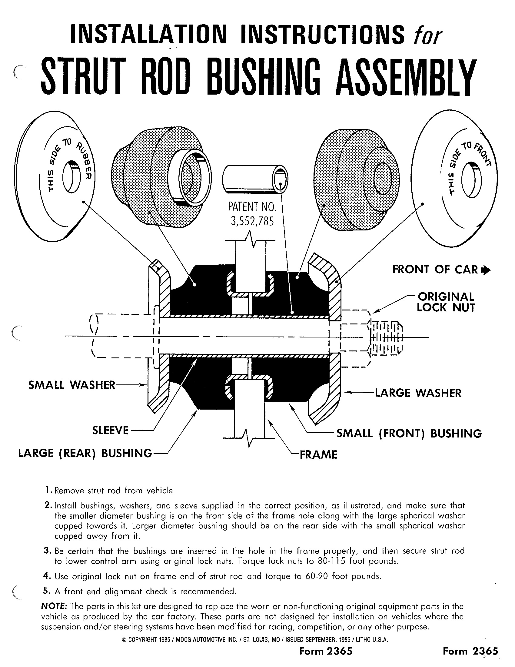
77-79 Strut rod bushing washer installation
Vacuum Wiper Motor Repair
Fuel Guage System Diagnosis
Seat Belt Light
Engine Installation & Break-In Checklist
Shift Lever Fix-It for all Thunderbirds from '58 thru 1966
If you are having trouble keeping your shift lever in the proper postion and it won't stay in park, the problem, more than likely is that the shift lever itself has a notch worn into it down on the end inside the steering column. You can repair this easily by pounding out the roll pin that holds the shift lever into the collar on the steering column and pulling out the shift lever. You will see that there is a one eighth inch notch worn into the flat part of the lever. Take this to a welding shop and have them weld it up and grind it down so that it matches the rest of the area near it. Put the lever back in and your problem should be nearly all solved.
Steering Column Bushing Replacement
There are a couple items in your steering column that can cause trouble.
One is the Nylon bushing at the lower end of the shift tube. If this is bad or gone you will have trouble trying to shift your car. The lever will not register correctly as to what gear you are in and you will also have trouble getting the car into park and low. If the shift lever fix doesn't solve most of your troubles then it is time to open the hood and find the shif tube and check to see if the bushing is bad. Click here to see the pictures of this. In order to replace the bushing you need to remove the steering column from the car and disassembled. This is not as bad as it sounds. If you have a shop manual you can refer to that. It does help. (If you do not have one, refer to the pictures on this site or you can order a shop manual by sending me an email).
Alternate Method---------------------
John, I wanted to let you know about my experience with steering column bushings and see what you thought. I have a '64 Bird and when I was getting it ready for the road in 1991, I found I had a bad bushing. By looking at it, I could see that the column would have to come out to do the job properly. I decided to try a gamble. I cut one of the bushings at what would be the bottom, snapped it over the shift tube and pushed it into place. Guess what? Its still there after 7 years and working fine. So maybe one doesn't have to remove the column to replace this bugger after all. What do you think?
--------------------------------------------------------------
It should also be noted that the Nylon Centering Cone at the bottom of the steering shaft does no more than keep the dirt out of the bottom of the column and serve as a cushion if the column or sector move enough to let the shaft bump against the side of the tube. The shaft should be held in place at all times by the fact that it is solidly mounted to the steering sector by the rubber coupler. This is not a critical part.
The other item is the Insulator around the upper bearing in the column. When this one is bad you may experience the ability to move the steering wheel up and down, the steering wheel may rub on the signal light collar on the column or you may feel a roughness when turning the steering wheel and this roughness you feel will seem to be right in the steering wheel. By referring to the picture (click) you will be able to see that there is a bearing (which seldom ever goes bad, just clean and relube it) and a plastic or rubber insulator around it. These are located just under the signal light switch. You need not remove the signal light switch to replace the insulator. You can gain enough slack in the wires to move the switch off to the side. Just look under the dash where the bundle of wires comes out of the column. Follow them down and remove the screws holding this harness to the column, then work the bundle up into the column a bit until you can manuever the switch off of the shaft and off to the side. You will need a snap ring pliers or be able to figure out a way to remove the snap ring holding the bearing onto the shaft. Most of the rest of this is pretty straight forward.
There is also a photo of the Lower Shift Tube Busing and the Upper Insulator on the picture page above.
Parts are available from Thunderbird Ranch and you can email me right here.
Removing broken off bolts
by : Paul Dakin
I run a machine shop/welding shop for about 25 years now and remove broken studs for a living. I get the broken bolt/stud AFTER somebody has locked it in with a drill bit or EZ out. Off center into the female threads. IF you are going to drill it out at least, PLEASE, drill on center. I would rather see one untouched. This is the pro-shop method: MIG welder, again on center of broken stud start a dot of weld and keep "stitching" i.e. dot-dot-dot-dot and continue until you have a little hill that rises above the surronding surface. Then place a flat washer that fits close to that over the "hill" and weld the "hill" to the flat washer. Then place a larger nut on the flat washer and plug weld in the nut hole to the washer until filled. While the whole thing is cooling tap-tap-tap on the nut top dead center with a hammer. Then take an air impact and socket and with the impact on the lowest setting start rattling the nut in a back and forth motion i.e. forward/backward. Slowly putting a little more pressure in the backward direction. This gets 98% of all broken bolts. Sometimes I will have to reweld 4 or 5 times but the heating cycle breaks the rust loose most of the time. The surronding material CAN be welded to so be careful. Aluminum or cast iron like blocks work best because MIG doesn't stick to it as well. A penetrater helps, we use old fashion liquid wrench but diesel fuel is great too. Be sure to run a tap in the threads after to clean out crap. This process can take the first couple of threads out but usually there is plenty of good ones deeper if you clean them out to full depth and use a length of bolt that uses all of the thread depth. One last note: 1 out of 10 broken bolts relieves themselves of pressure when the upper part snaps and the remaining "stud" is really quite loose now and can be removed with a small prick punch and small hammer if you drive it counterclockwise carefully. All of the above have been used on bolts from 8-32 to 1 1/2" , of course the larger the eaiser but small ones like 6mm and larger work well to.
Vinyl Roof Covering Installation
Vinyl tops are not hard to install correctly.
They are time consuming and require some patience.
There is a special contact cement made for vinyl tops and is available from good auto trim shops or their suppliers.
All the trim must be removed including the drip rails around the sides and the trim at the base of the roof where it meets the quarter panels. Removing all the trim is more than half the battle. The windows need not be removed.
If you have trim all removed and the old top removed, and the roof cleaned and painted nicely and the paint is well cured......................then.................
Lay the top covering in postiion so the center line of the top is centered down the center line of the roof of the car. Tape it down to the front and the rear glass very well.
Start with one side and lift it up and fold it over the other side (it is a good idea to cover the material with heavy masking paper or plastic before laying this side over the exposed side). This will put the underside up so you can apply the glue to the roof and to the underside of the covering that will be applied to that side of the roof.
Then............(you should have a trusted friend helping you)........when the glue is set properly you will have to lift the top material up and hold it over the area to glue it onto and slowly and carefully squeegee it down working from the centerline outward evenly from front to back keeping the remainder of the top from touching the glue until it is to be squeegeed down.
This process should be carried out for the remainder of the roof. The edges should be trimmed leaving enough to glue down under the trim.
EASY.......HUH? IF I CAN DO IT YOU ALL CAN TOO. (if you make a mistake you can pull the material up right away for a quick retry)
Non - operational Power Windows
If your power windows do not operate on your car there are a number of possible causes. It is important to know what these are in order not to buy parts you will not need.
The obvious things to check are whether or not you are getting power to the switches and to the motors themselves. If you put your ear to the door and operate the switches listen if there is any sound inside the door. If you hear a bit of a thump sound then your window motors are getting power and are probably stuck. If you hear a whirring sound you probably have a busted gear in the window motor assy. These can be replaced seperate from the motors. ( I have new ones in stock) If you hear nothing you either are not getting power to the motors or the motors are bad.
One of the quirks about the 64-66 Birds that I have found is that the windows in the doors tend to stick in the total up position once in a while. This is caused by lack of lubrication and maladjustment in the upper stops on the door. The way to check for this is to remove the door panel of the non-operational window , shake the window and tap on the area of the stops with a wood hammer handle or similiar object .If this does not get it to work then loosen the 4 bolts that hold the regulator assy. to the inner part of the door enough so that the window can be shook loose from the stops. If this fails to change anything then you need to check further.
Another cause for the sticking in the up or down position is the motors having bad connections internally to the armature. Some of this can be solved by loosening the adjuster screw for the backlash on the end of the little gearbox on the motor itself. If you just back it off about a quarter or half turn this will help let the armature move a bit to make a contact when you hit that switch. To change the adjustment however you will have to remove the motor/regulator assembly from the door.
If you need help or advice in this situation, just give me a call or email me.
Exhaust Manifold Tips
The exhaust manifolds on the 352's and the 390's are notorious for leaking and cracking and are a headache to remove.
One of the reasons these manifolds cracked is the formation of rust in the narrow area between the head and manifold in the areas where the spark plugs are. This happens when dirt fills this crack and water can build up in there. Clean this out if possible once in awhile.
To remove the manifolds you must remove the four bolts on the top side and these may need to have the boss on the head casting itself heated with an acetylene torch to prevent the bolt from snapping off. The four lower bolts normally do not twist off.
If you have your manifold off, make sure you take it and the head and have the mating surfaces machined to make sure they are flat. This is the first bit of cheap insurance. The second thing to do is to purchase a set of gaskets, Fel Pro is a good brand. You will want to get some anti seize compound for the bolts while you are at the Auto Parts store. Also, now do not laugh, go purchase some furnace gasket cement from your local hardware store. When you get ready to assemble the manifold onto the head put a thin coating of the furnace cement on both surfaces and then install the manifold with the gasket, making sure to use the anti seize compound on all the bolts.
Another good gasket number is Fel Pro #1442.
The heat shields used on these cars have the following part numbers C2SE-9448-A for the right hand side and C2SE-9448-B for the left hand side. These are available from Ford dealers yet.
Transmission Tech Tips
FMX Tech Tips
* This trans is very sensitive to dirt. Make sure all parts are spotless. Especially the governor.
* On early Cruiso's, A 350 output shaft plastic bushing will work in place of those difficult to work with needle bearings on the servo.
* Install the bands before installing any drums.
* A tool is very helpful when installing the pistons in the drums.
* Don't lose the needle rollers in the forward drum.
* Don't drop the servo band struts into the trans when installing them.
* Put a load on the servo when tightening them.
* Use transjel to hold the struts to the servo levers.
* Use a small rubber hammer only to tap the pipes in place.
* Removing the top plate on the main vb makes it easier to install the one servo and its pipes.
* Make sure to change the linkage seal on the bench. It is not easy doing it in the car.
* Be careful not to break a ring when installing the drums.
* Must be careful when changing flywheels. If a C-6 flywheel is used the converter will push the pump gears into the stator support.
* Correct size front servo seals are a must. Although under size seal will fit but stretching causes leakage. The common complaint is late shifts as the vehicle warms up.
* Check servo by blowing air thru release side of servo and check for leaks around cover bore
* Some late model units used a media filter rather than the screen type. These units have a bleed hole in ther pressure regulator. Using the media filter without this bleed hole can cause noise and restrict fluid flow.
* Use dexron fluid in this trans.
C-6 Tech Tips
* Check outer pump gear for digging into pump housing
* Remove the spring in the stator for full time lube. Ball must roll back and forth.
* Forward clutch apply plate will install in place of direct clutch pressure plate. This will convert a 3 clutch drum to 4.
* Leaving out the cushion in the forward drum will convert a 4 clutch forward drum to a 5 clutch drum for heavy duty use.
* The best band adjustment is 3/4 to 1 full turn.
* There are 4 different servo covers. They are "P,L,S,N" Ranging from the heaviest duty to the lightest duty. "p" is for heavy duty only.
* The rare "F" lever is finally available again from Aceomatic trans parts in Phoenix! It is a Must for extreme duty units.
* There are numerous vb kits available for the C-6 trans.
* Make sure you note which direction the linkage was facing before removal.
* If there is a reverse check ball in the vb, then its OK to use a reverse piston without a checkball and vice versa.
* Install the reverse piston in the bottom of the case with the checkball towards the top to bleed off any air.
* A late vb will install on an early unit, But an early vb will not work on a late unit.
* Always count the speedo teeth on the output shaft when changing over to a shelf unit. There are 4 different tooth counts.
* The longer the modulator pin the higher the line pressure. There are many different lengths.
* Do not mix and match early and late forward drums. The bearing pocket is different. The 3 piece torrington is the early style, while the one piece torrington is later. When rotating the front planet, it must sit on the bearing. There must not be a gap between the planet hub tip and the bearing. If there is a gap there, then you have mismatched parts. It will come back with the washer wiped out.
* E4OD planets will install into a C-6 for a lower 1st and 2nd, but the entire assembly must be used including the shell.
* Always check to make sure the accumulator springs are not broken in the vb. Very common..
* Installing a check ball in first, then installing the cutback valve will firm up shifts.
* Make sure the tv lever springs back and forth after installing vb.
* Flat file vb surfaces to remove any high spots.
Restricting the Surplus of Oil to the Top end of the Engine
To restrict the top end oil in the FE engine, just take off your rocher arm shafts. Drop in a .090 thousands Holly jet and you have solved your problem. They seem to be made to fit in with no drilling or tapping.
Throttle Linkage Problems
(Click here for diagram)
Many problems that are related to the throttle linkage can be solved just by seeing what it is supposed to look like. Many times someone works on the car and leaves off some of the parts and you don't have a clue to what is supposed to be there. Well, take a look at the picture and see if yours looks similiar. Then if you have to call someone (me even) you will be able to refer to the diagram and discuss what you see with a bit of knowledge of how this compares to your set-up.
Fuel Guage System Diagnosis
To test the fuel guage system you will need to do a few things and watch the results
disconnect the wire at the sender on the tank and connect it to a good ground. Then check to see what your guage does. If it goes all the way to full then the problem is either the sender or a poor ground from the tank to the body. To test this connect a jumper wire from the tank to the frame or body making sure you have good clean connections. Then re-connect the wire to the sending unit and see what your guage does. If it now works then the trouble is the ground. If not it is the sender.
If you did not get a full reading with the wire off the sender and grounded then you need to check up under the dash. You will need to test for current at the instrument voltage regulator (IVR) ( or referred to as the constant voltage regulator--CVR). This is typically located on the back of the instrument cluster unit. With the ignition key in the on position you should get 12 volts on one side and 5.0 volts on the other side. These are aprox. readings. If you do not get these readings check further. Looking at the diagram you can see that you should have the 12 volt reading all the way from the battery to the IVR then it turns to 5.0 volts. Where ever you lose the reading that is what the problem is in your system
If you find that your guage is giving you a faulty reading, there is a way to adjust it. Tim Marek turned me onto this and it applies to the Bulletbirds. However you might closely inspect yours if it is a dif. year. There may be a similiar way to adjust yours.
To adjust the fuel gauge to full if gauge otherwise works ok.
Remove the gauge set from the dash, set carfully face down, remove the
tin plate from the back (this is the plate that holds the bulbs) be
carefull not to loose or break the insulating gaskets under the four
nuts. Once this plate is removed you will see four holes in the back of
the gauges (about 1/8" Dia and they look like a little gear inside of
them) One adjusts the low and the other adjusts the high, you will have
to have the tank full, hook up the four wires and turn on the key, very
carfully insert a small screwdriver and turn the gear to adjust to full.
CAUTION: Turn the gear a very small amount. You might have to play with
both adjustments to obtain the correct setting.
Seat Belt Lights in 1964 -1966
The seat belt light on the 64 and the early 65 were conrolled by a push swich located inside the light unit. You tap the lens and the light would shut off.
Somewhere along the line in 65 they also used a switch in the seat belt retractor that was supposed to shut this off. Obviously in those years when we did not like wearing seat belts there was enough complaining that Ford changed it again by installing a time delay relay that would wait for about a minute then turn the light off automatically
Some of the early 1966 cars may still have the retractor switch.
The relay is about 1/2 inch by 2 inches long and is located up under the dash by the steering column.
Broken Button on Power Seat Switch
The biggest problem with power seat switches on Thunderbirds is that the center button breaks off. You end up with a perfectly operational switch that has no operator. I have successfully repaired a good number of these already using the following method.
Carefully drill a tiny hole into the piece of the switch where the button broke off from, about 1/16" dia. and about 1/8" deep. Then drill a hole the same size into the button (or some similiar button that will replace the broken off one) only this one should be a bit deeper. Now get a piece of steel pin or wire about 1/16" dia and cut to length so that both pieces of switch fit together with this pin between them. You will need some good epoxy glue. Clean you parts very well then apply some epoxy to all of them being very careful not to get any more on them than necessary. If you do you will glue your switch together so it will never operate again.
Let it set really good and you will be able to operate it for years to come.
Polishing Plastic Lenses
One of the best things to use to polish up plastic lenses and parts is toothpaste. Use a soft cloth and add toothpaste often, sometimes a touch of water will help.
If the scratch or defect is a bit deeper you can use some 1500 grit sandpaper, (wet or dry type works best with some water) to level the area prior to polishing. Never just sand the tiny area that is damaged. You need to sand a large enough area to keep it smoothed out around the damage so you don't end up with a dip in the plastic when polished out.
Foamy Power Steering Fluid - Bleeding out the Air
The foaming problem is caused by air in the lines. Getting the foam out of there is rather easy if you know how. Just keep in mind that the reservoir level will go down as the engine runs, then come back up when the engine stops. With "good" fluid it will do this a little; with "foamy" fluid the level will move a lot, and high tide may overflow, worsening the situation.
The trick is to not let the level ever get so low as to allow air into the lines. To fix it, start by filling the level. If it's down very far, suggest filling it above that one-inch suggested fill level. Start the car, then check the level again. It will have dropped, but unless it's in danger of allowing air into the pump, it's okay. Next turn the steering wheel one direction, then check the level again and fill if necessary. Then turn the wheel the other way and check/fill again. Straighten the wheels and turn on the wipers. Check level again. You may have to do this a number of times to get all the air out. On models with a filter inside the reservoir you can run the engine with the cover off and observe the fluid as you cycle the steering slowly. Keep the wipers on during all of this to keep fluid circulating through that system flushing out any air. Allow the motor to run about 5-10 minutes if it hasn't done so already, then shut it off. Observe the level, and add fluid if it happens to be below an inch from the top. Reinstall the lid, you're done. That is unless you suspect a leak, in which case you should have fixed it before going to all this trouble.
Removing Frost Plugs Easily
Just one bit of info regarding these frost plugs. Many people are under the impression that you have to pull the old ones out.
My dad taught me-----
Pound them in and the will lay right at the bottom of the water jacket then you can just reach in with a channel-locks or pliers and pull them out sideways. Very easy to do. Do not worry about losing them inside the engine, as they cannot go anywhere. the bottom of the water jacket is right there by the holes. I cannot remember ever pulling an engine to change frost plugs. We always managed somehow to replace them with the engine in the car.
One note from the rebuilders on sealing them--use the hardening type of permatex in a tube.
Brake fade and/or soft pedal
Regarding brakes that fade'''''
One thing overlooked by most is the fact that if your brake drums have been "turned or cut", you now have oversize drums and you do not have oversize shoes. This problem is usually solved by "arcing" the brake shoes to fit the oversize drums.
To illustrate this take a small tin can and put it inside a larger tin can. No matter where you make the cans touch, you only have a small surface touching.
If you find a really good brake shop or automotive machine shop that does brake work they will know what you are talking about. You will need to take the brake drums and the shoes for that specific wheel in as a set and when you put them back on the car they need to be installed as a set on that wheel. In effect you are getting your shoes and drums custom fit. Over the years people cut the drums, install new shoes and never think of this. If done too many times you will end up with the problem you describe.
Water Leaking into the Trunk - 64-66
If you have a constant problem with water getting into the trunk of your 64-66 Hardtop there are 3 main things that you should check.
1). The weatherstrip first of all. This is usually not the problem as there is a pretty good trough around there to direct the water out.
2). The rear vent drains either plugged or rotted and leaking into the trunk. These are now available new (I do supply them, about $60.00 per pair). You should also check for rust arount these drains.
3). A most unlikely culprit is the trunk lock assy. If this has ever been removed, more than likely whoever did it cleaned it up nicely before installing, thereby removeing all the caulk that kept the water out. There must be a good bead of caulk all around where it contacts the trunk lid surface. Then there is the little drain that goes out the back edge of the underside of the trunk. There should be a plastic sleeve with a flange held in place with 2 screws. This usually gets tossed also as it don't look real useful. This must be caulked where it slides onto the lock assy.
1970 to 1972 Vacuum Diagrams
If you click on the link below you will download 2 diagrams that cover the complete vacuum system on the 1978 Thunderbird. One diagram is for the cars with Automatic Temperature Control and the other is for the Standard Air Conditioned Cars. If you do not have air then that part of the daigrams do not pertain. The rest will be the same. These are especially good for the headlamp door circuit diagnosis.
click here to download
1978 Vacuum Diagrams
If you click on the link below you will download 2 diagrams that cover the complete vacuum system on the 1978 Thunderbird. One diagram is for the cars with Automatic Temperature Control and the other is for the Standard Air Conditioned Cars. If you do not have air then that part of the daigrams do not pertain. The rest will be the same. These are especially good for the headlamp door circuit diagnosis.
click here to download
disclaimer:
I am not the expert in any of this and I recommend you think before you act. These are just suggestions and tips that have worked for me. I have different skills, tools and facility than you so you have to choose for yourself what will work best for you.
back to Thunderbird Ranch Site Index